ZTC: Zero-Trust Continuum
A zero-trust security architecture for the edge-fog-cloud continuum, applied to critical energy infrastructure. Where should access decisions be made, which credentials fit a moving system, and how does trust follow a service when it migrates?
My main personal project, and the one that best shows the kind of work I want to do: designing how a system should be structured, how access and trust are handled across it, and which trade-offs are made between security, performance and robustness. It is also a candidate topic for my master’s thesis. That is still an idea at this stage and not settled.
This page walks through the design from the big picture down to the individual building blocks. All the diagrams are ones I drew while planning the project. They are early working drafts and will change as the code catches up, but they show how I think about the system and how I plan to build it. Each diagram is meant to make sense on its own, and the text around it is there to help you get into it quickly. Click any diagram to see it in full size.
At a glance
- What: a zero-trust security architecture for systems that are spread over field devices, local servers and the cloud.
- Where: a digital power substation, where a wrong or slow access decision has physical consequences.
- Core idea: nothing is trusted because of where it sits on the network. Every single request is checked, and trust is re-evaluated all the time.
- Built with: Go, C++ with OMNeT++, Python, Docker, Kubernetes, Terraform, Ansible and Cisco IOS.
- Standards: NIST SP 800-207 (zero trust), IEC 62443 (industrial security), IEC 61850 (substation communication) and MITRE ATT&CK for ICS.
- Status: early. The design is in place, and the foundation and the first decision-making parts are implemented.
The problem
Zero trust (“never trust, always verify”) is well established in the cloud, but it quietly assumes a stable, well-connected and centrally managed infrastructure. Fog and edge computing break those assumptions:
- devices join and leave all the time
- links can be slow, or cut off from the cloud entirely
- nodes may be owned by different parties
- tasks move between edge, fog and cloud while the system is running
Every time a task moves, the set of components that can see or touch its data changes, so the trust boundary has to be redrawn. In critical infrastructure such as the power grid this matters a lot. A wrong decision can cause an outage, and adding too much delay means a protection function reacts too late.
The scenario: a digital substation
ZTC models a smart-grid substation spread over three layers:
- Cloud (the control centre): issues identities, makes access decisions, stores telemetry and runs monitoring.
- Fog (the substation itself): local servers that enforce access, run tasks close to the devices and watch for intrusions.
- Edge (field devices): measurement units, smart meters, circuit breakers, remote terminal units and EV chargers, all simulated.
Between each layer there is a trust boundary. No component trusts another because of where it sits on the network. Every request carries a verifiable identity, is judged by a policy that also looks at how trustworthy the sender seems right now, and is enforced before it reaches anything that matters.
How to read the diagrams
The same visual language is used in every diagram, so a colour or line style always means the same thing.
| Element | Meaning |
|---|---|
| Blue | cloud / control centre |
| Green | fog / substation |
| Orange | edge / field devices |
| Purple | the buffer zone (DMZ) and wide-area network between substation and control centre |
| Red | an attacker, a security-critical control or a known limitation |
| Yellow note | why something is designed the way it is |
| Solid black arrow | a request or data on its way |
| Dashed red arrow | a trust signal (the system re-checking itself) |
| Dashed blue arrow | control traffic, such as “throw away old decisions” |
| Thick green arrow | measurements on their way to the control centre |
| Dotted grey arrow | a copy of traffic, sent for inspection |
| Numbered circle | a step of the zero-trust cycle |
| Thick dashed red line | a trust boundary |
The big picture
This is the finished system I am working towards. Everything else on this page is a zoomed-in part of this picture. It comes in two versions: a simple one that shows the overall idea, and the full target architecture.
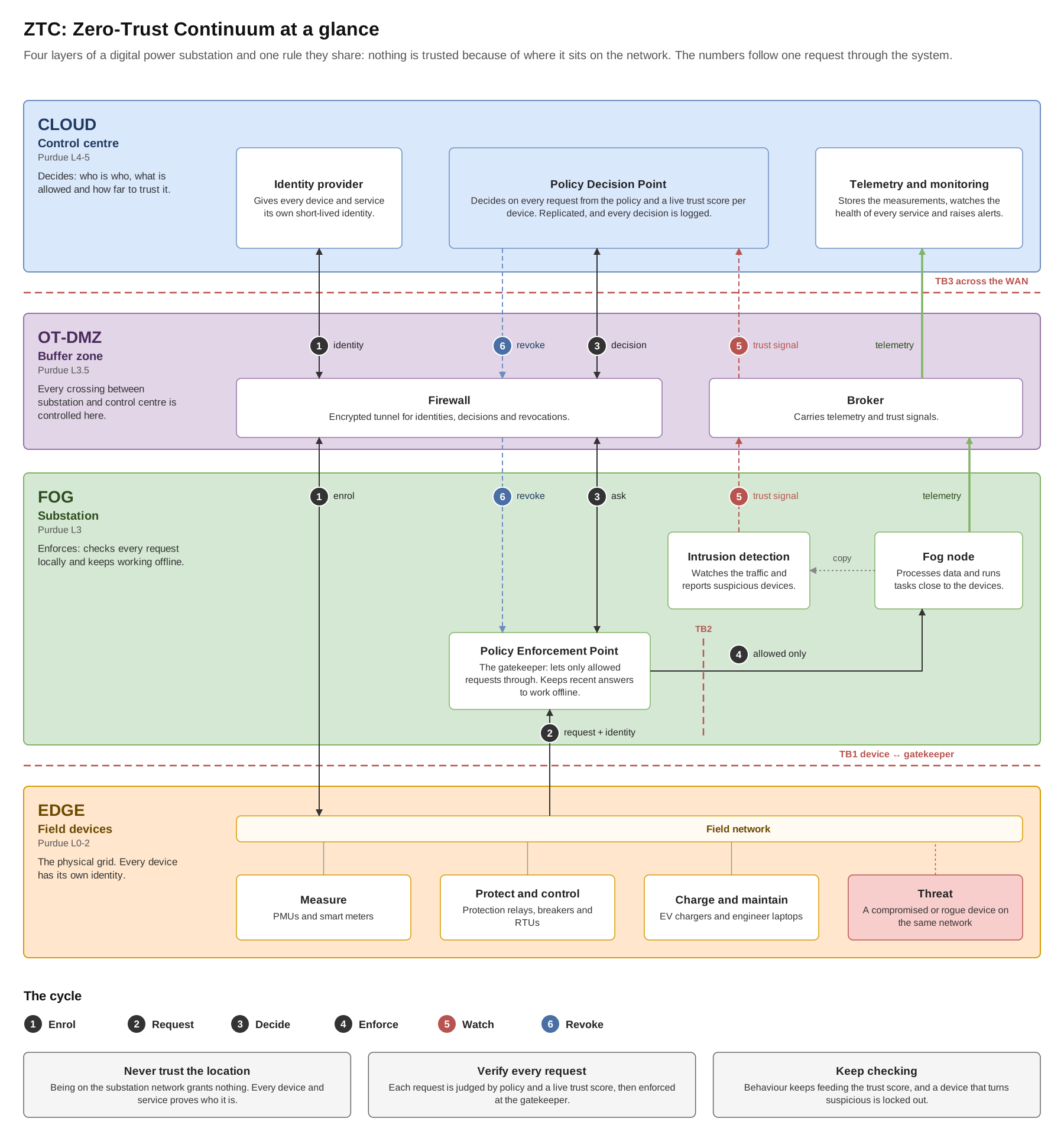
Each layer has one job:
- Cloud (the control centre) decides. It gives every device and service its own identity, judges every request against the rules and a live trust score, and keeps the measurements and the records.
- OT-DMZ (a buffer zone) controls every crossing between the substation and the control centre. A firewall with an encrypted tunnel carries identities, decisions and revocations, and a broker carries measurements and trust signals.
- Fog (the substation itself) enforces. A gatekeeper, the Policy Enforcement Point, checks every request close to the devices and remembers recent answers, so it keeps working when the connection to the control centre is cut. Next to it, the fog node processes data and an intrusion detection system watches the traffic.
- Edge is the physical grid: devices that measure, protect and control, charge and maintain. Every device has its own identity, and an attacker can sit on the same network.
The numbers follow one request through the system, from the moment a device gets its identity to the moment it is locked out. The six steps are described under the full diagram.
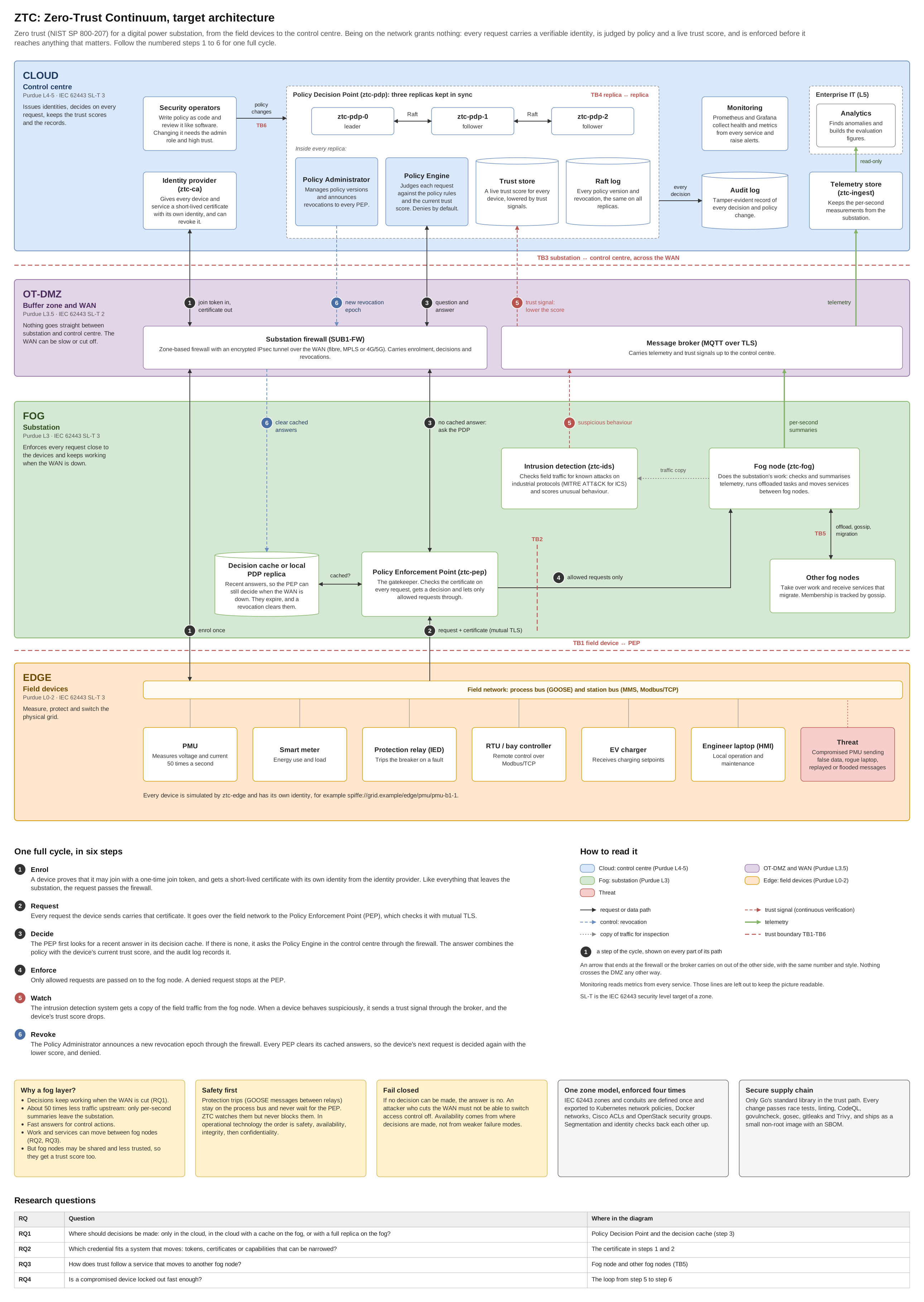
One full cycle, in six steps
- Enrol. A device proves that it may join with a one-time join token, and gets a short-lived certificate with its own identity from the identity provider. Like everything that leaves the substation, the request passes the firewall.
- Request. Every request the device sends carries that certificate. It goes over the field network to the Policy Enforcement Point (PEP), which checks it with mutual TLS.
- Decide. The PEP first looks for a recent answer in its decision cache. If there is none, it asks the Policy Engine in the control centre through the firewall. The answer combines the policy with the device’s current trust score, and the audit log records it.
- Enforce. Only allowed requests are passed on to the fog node. A denied request stops at the PEP.
- Watch. The intrusion detection system gets a copy of the field traffic from the fog node. When a device behaves suspiciously, it sends a trust signal through the broker, and the device’s trust score drops.
- Revoke. The Policy Administrator announces a new revocation epoch through the firewall. Every PEP clears its cached answers, so the device’s next request is decided again with the lower score, and denied.
Choices that shape everything
- Deciding and enforcing are separate jobs. One central place holds the rules and makes decisions, and lightweight gatekeepers sit next to the workloads. A compromised gatekeeper cannot change the rules.
- Identity, never location. Being on the substation network grants nothing. A rogue laptop plugged into the substation is exactly the threat.
- Fail closed. If the decision service cannot be reached, the answer is no. An attacker who cuts the network cable must not be able to switch access control off.
- Safety comes first. Protection signals that trip a breaker within milliseconds are observed, but never delayed by access checks.
The four design questions
The project is built around four open questions. Each one comes from a way the fog differs from the cloud, and each one is answered with measurements at the end.
| # | Question | Where on this page |
|---|---|---|
| RQ1 | Where should access decisions be made? In the cloud only, in a hierarchy with a cache on the substation, or with a full copy on the substation. What does each cost in speed, availability when the network is down, and how out of date a decision can get? | Where decisions are made |
| RQ2 | Which kind of credential fits a moving system? Tokens, certificates or capabilities that can be narrowed down. Overhead, how fast they can be revoked, and how they pass along a chain of tasks. | Identity and encrypted connections |
| RQ3 | How does trust follow a service that moves? Re-authenticate from scratch, prepare the new host in advance, or hand over a short-lived ticket. Downtime against exposure. | When a service moves |
| RQ4 | Does continuous checking catch a compromised device fast enough? How quickly a device that is logged in but misbehaving is locked out. | Catching a compromised device |
The decision chain: how one request is judged
Milestone M1. This is the heart of zero trust: the chain from a request arriving to a yes or no.
Zero trust, by the book
The design follows NIST SP 800-207, the US standard that describes zero trust. A simple way to picture it: every door in a building has a guard (the PEP). The guard does not decide anything alone, but calls a central desk (the PDP) that knows the rules and everyone’s current standing. The desk decides, the guard enforces, and the guard lets exactly one approved visit through at a time.

The two halves: gatekeeper and decision point

One request, step by step

How the rules decide

Why it is designed this way
- Rules based on attributes, with trust as one of them. Roles say who. Zero trust also needs where (zone), when (time, emergency) and how much (trust). Putting the trust score in as an ordinary attribute keeps the rules simple.
- A deny always wins, and the default is deny. Adding a rule can never open something another rule closes, and a broken rule makes the system stricter, not looser.
- The decision point owns time and trust. If the caller could send them, it could replay old timestamps or claim to be more trusted than it is.
- Short answers for dangerous actions. Permission to operate a breaker is only valid for 10 seconds, and emergency access for 1 second, so those decisions are made again often.
Where should decisions be made?
Design question RQ1. The same gatekeeper and the same rules, in three different placements, chosen with one setting.

- Cloud only: always up to date, but if the connection to the control centre is cut, everything is denied.
- Hierarchical (the default): a cache on the substation answers repeated requests locally, and the cloud is asked only when needed. During an outage, recent answers survive for a short time.
- Copy on the substation: keeps deciding during an outage, at the cost of keeping copies in sync and putting more on a less protected machine.
This is the classic trade-off between consistency and availability. What I would pick for a real utility: hierarchical by default, a local copy at sites with unreliable links, and short lifetimes on dangerous actions everywhere. Whatever the choice, the system never opens up to stay available. Availability must come from placement, not from switching access control off.
Catching a compromised device
Milestone M2, design question RQ4. A device with valid credentials can still be compromised. This part closes the loop that makes the system zero trust rather than a perimeter: watching behaviour and acting on it.
The data pipeline

The fog node sees every raw reading (50 per second), so detection does not depend on the cloud connection. Only summaries cross the network, about 50 times less traffic.
No single point of failure
Milestone M3. If the decision point is one machine, it is one machine to break or attack. This part spreads the system over several machines, using the same algorithms I work with in my distributed-systems course.
A replicated decision point

Knowing who is alive

Where device data lives

Putting events in the right order

A design point worth noting: membership information is only a hint about who is alive. It never grants access. The gatekeeper still decides every call.
Placing work and running it safely
Milestone M4. Choosing where to run a task, and packaging the whole system so that the network separation is built in.
Trust-aware offloading

A fast but untrusted node is never chosen, and nodes below a minimum trust level are excluded completely, so the cost model can never be tuned into an unsafe choice.
Zones and conduits
Milestone M5. Industrial networks are split into zones with controlled crossings between them, called conduits, following the IEC 62443 standard. ZTC uses both: network separation shrinks what an attacker can reach, and identity checks stop the attacker who is already inside a zone. The design follows the ISA/IEC 62443-3-2 process, the same way I used it for the WannaCry case in TEK5520.
The first requirement (ZCR 1) identifies the System under Consideration (SuC). Here it is one digital substation and what it talks to: enterprise IT, the control centre, the WAN between them, a buffer zone (OT-DMZ), the substation fog servers, the station bus with its field devices, the process bus with the protection relays, and temporary vendor access. The second (ZCR 2) is the initial risk assessment, where risk is likelihood times impact. In a flat substation network one rogue laptop or one compromised device can reach the breakers, and the impact is loss of grid control or safety, so the risk is above what a utility would tolerate (ZCR 4). That makes partitioning into zones and conduits necessary (ZCR 3).
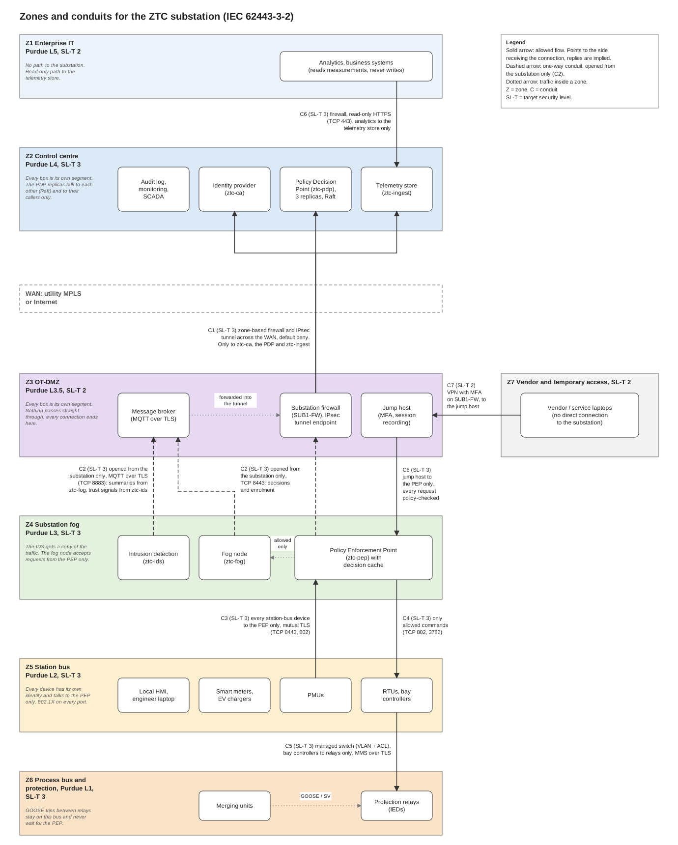
The figure shows the proposed design. Seven zones separate assets by function and trust, and inside each zone every box is its own segment with no traffic between the boxes except where an arrow is drawn. Enterprise IT (Z1, Purdue Level 5) holds analytics and business systems and has no path to the substation at all, only read access to the measurements. The control centre (Z2, Level 4) holds the parts that decide: the identity provider, the three replicas of the Policy Decision Point, the telemetry store, and the audit log, monitoring and SCADA. Between the control centre and the substation lies the WAN, which is treated as untrusted because it can be slow, cut or listened to. The OT-DMZ (Z3, Level 3.5) is the buffer zone, with the substation firewall that ends the encrypted tunnel, the message broker and a jump host with multi-factor authentication and session recording, so that nothing outside the substation talks directly to the devices. The substation fog (Z4, Level 3) holds the Policy Enforcement Point, the fog node and the intrusion detection. The station bus (Z5, Level 2) holds the field devices that send data and receive commands, and every one of them has its own identity and talks only to the PEP. The process bus and protection (Z6, Level 1) is its own zone, because the protection relays must be able to trip a breaker within milliseconds, and those GOOSE messages stay on that bus and never wait for an access check. Vendor and temporary connections (Z7) get a zone of their own, so a service laptop is never plugged straight into the substation.
The conduits carry the main improvements, and each is drawn with what enforces it and a target security level. C1 is the only way between the substation and the control centre: a zone-based firewall and an IPsec tunnel across the WAN, default deny, that reaches only the identity provider, the decision point and the telemetry store. The broker does not have its own way out, it forwards measurements and trust signals into the same tunnel. C2 connects the fog and the OT-DMZ and can only be opened from the substation side. The PEP asks for decisions and enrolment through the firewall, and the fog node and the intrusion detection send summaries and trust signals to the broker, so nothing on the WAN can open a connection into the substation. C3 and C4 are the zero-trust part: every device on the station bus may only talk to the PEP over mutual TLS, and only commands the PEP has allowed go back down. C5 is a managed switch with VLANs and access lists that lets only the bay controllers reach the protection relays, using MMS over TLS. Vendor access takes two conduits and never reaches a device directly: C7 is a VPN with multi-factor authentication on the substation firewall that leads to the jump host only, and C8 lets the jump host reach the PEP only, so every maintenance request is checked against the policy like any other request. C6 lets analytics read the telemetry store over HTTPS and nothing else. In terms of the foundational requirements, the conduits address restricted data flow (FR5), the identities and the PEP address identification and authentication (FR1) and use control (FR2), and the intrusion detection and the audit log address timely response to events (FR6).
The target security levels in the figure (SL-T 3 for the control centre, fog, station bus and process bus zones, SL-T 2 for enterprise IT, the OT-DMZ and vendor access) are proposals. SL-T 3 is the usual target for protection and control in a substation, while the other zones hold no control functions. A conduit is given the higher level of the two zones it connects, so every conduit is SL-T 3 except C7. This rule is my own assumption, and the jump host sits in an SL-T 2 zone while giving a path towards SL-T 3 zones, which is why it needs multi-factor authentication and may reach only the PEP. All levels are meant to be confirmed in a detailed risk assessment (ZCR 5), which would need data from a real utility.
Physical security completes the design, because a network control is weak if someone can plug a laptop into the substation network. The fog servers and network cabinets should sit in locked rooms or cabinets with access logging, unused switch ports should be disabled or moved to a parking VLAN, and every port that is in use checks the device with 802.1X before it gets on the network. The last two requirements (ZCR 6 and 7), documentation and approval by the asset owner, should name who owns each firewall and switch rule. In ZTC the zone model is written once in code and the firewall, switch, container and Kubernetes rules are generated from it, so the documentation and the rules cannot drift apart.
Identity and encrypted connections
Milestone M5. Every device and service gets its own identity, carried in a short-lived certificate.

The names describe what a workload is (layer, type, name), not where it is, so they survive address changes and migration, and the same name is used both for the encrypted connection and in the access rules. The private key never leaves the device, and a device cannot pick its own name.
When a service moves
Milestone M6, design question RQ3. When a running service moves from one fog node to another, the trust boundary moves with it. The new host must get exactly the rights the service had, the state must not leak on the way, and the old host must lose access.

Proving it with numbers
Milestone M6. The running system shows that the design works. A simulation answers the design questions with numbers, because it can vary network delay, outages, scale and attack timing in controlled, repeatable experiments.


Real infrastructure and network
Milestone M7. Showing that the same zone model holds all the way down to switches and routers, and that the whole setup can be rebuilt from the repository.
The network: my initial plan
I want to build the substation network on real Cisco equipment, so that the zones above are not only rules in software but also separate networks on the router and switches. Each zone gets its own VLAN. One router at the edge of the substation works as the firewall between the substation, the buffer zone and the outside, and it carries the encrypted tunnel to the control centre. A core switch moves traffic between the zones and only lets through the crossings the zone model allows. The switch that the devices plug into checks every device before it is let onto the network, so a laptop that someone plugs in gets nowhere.
Why: zero trust checks every request, but the network is still the first barrier. If the PEP has a bug, the network should still stop a device from reaching things it has no business with. Building it on real equipment also shows that the design works outside a simulation.
Rebuilding everything from code: my future plan
When I get this far, the goal is that the whole setup can be built again from the repository with a few commands, instead of by hand. Terraform will create the machines and one network per zone. Ansible will then set up and harden the machines and install Kubernetes. Last, the ZTC services are deployed on top, also on Raspberry Pis that act as fog nodes. To test without Cisco equipment, the same network can run as a free lab on a laptop. The clocks on every machine must also stay in sync, because the short-lived certificates stop working if the clocks drift apart.
Security in the delivery pipeline
Security checks are part of every change, not a separate phase at the end.

- Several overlapping scanners, because each finds a different kind of problem: risky code patterns, known vulnerabilities in dependencies and images, and leaked secrets.
- The end-to-end demo is a test. If a change lets a compromised device keep its access, or breaks the audit log, the build fails, even if every unit test passes.
- Minimal images with a parts list (SBOM), so there is less to attack and it is easy to check later whether a new vulnerability affects them.
How it is built
The plan is one shared model (trust score, policy rules, credentials, decision cache, migration protocol) that exists in two places on purpose: a reference implementation and a simulation used for evaluation.
- Reference implementation in Go, standard library only, so the cryptography, the replication log and the APIs stay readable end to end
- Simulation and evaluation in OMNeT++ with a C++ core, recording the latency, availability and security signals the design questions ask about
- Deployment with Docker Compose and Kubernetes, infrastructure as code with Terraform and Ansible, monitoring with Prometheus and Grafana
- Analysis in Python: result parsing, telemetry features and anomaly detection
It also works as a companion to my current courses: it pulls together fog offloading and placement from IN5700, consensus and replication (Raft, gossip, Chord) from IN5020, and industrial security standards and zone models from TEK5520.
Status
This is a long-running project and it is early. Here is where it stands:
- Done: the full architecture and the diagrams on this page, the repository foundation with CI, and the shared service base (M0).
- In progress (M1): the policy engine, the trust score and the decision service are implemented and tested. Signed tokens and narrowable capabilities are being added now, with the gatekeeper next.
- Ahead: the fog node and intrusion detection, the distributed-systems parts, containers and Kubernetes, the industrial security work, and finally the simulation and evaluation.
The diagrams are first drafts and will be updated as the implementation moves forward. Progress is tracked openly in STATUS.md in the repository.